Assembly instructions
Note: Program the Wemos D1 mini before soldering it onto the PCB. Once the circuitry is assembled, Q1 pulls the serial RX line low. This interferes with communication over USB. If it is ever necessary to reprogram the device after it has been built, place a jumper on the JP2 header before programming. Remove the jumper when programming is complete.Soldering
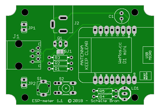
The PCB was made with some possible future additions in mind. For standard functionality, the following components are not needed: J2, C1, R3, R4, R5, LD1. Also only either S1 or S2 would normally be installed.
 Components:
| Q1: | BC548A |
| R1: | 1 kΩ |
| R2: | 10 kΩ |
Optional: |
|
| R3: | 10 Ω |
| R4: | 150 Ω |
| R5: | 100 Ω |
| LD1: | Bi-color LED, common cathode |
It is generally easiest to build a circuit from the lowest components upward. So, start by putting some solder on SJ1 so the two pads are electrically connected. Next, solder R1 and R2 onto the board. Make sure not to mix up the two. The color bands may look very similar, but the resistors have different values. R1 is 1 kΩ (brown-black-red), R2 is 10 kΩ (brown-black-orange). Use a multimeter to check the values if unsure which is which. Then install JP1 and JP2 and the male headers for the Wemos D1 mini. Next, solder the push button (S1 or S2) and Q1 onto the circuit board. Orientation is important for a transistor. It must match the outline drawn on the circuit board. Before installing the Wemos D1 mini, refer to the appropriate section below, depending on which enclosure is going to be used.
Enclosures
Kemo case
The PCB was designed for the G026N case, manuactured by Kemo Electronic. Some holes need to be made in this case for the connector(s) and the LED.With the RJ12 connector (J1) installed on the PCB, insert the board into the box. Using a sharp knife, mark the edges of the connector on the box. Remove the PCB and use the knife to cut out some plastic to make room for the connector. Frequently check the fit using the PCB and connector. You can also use a small file to refine the cutout. A nail file works well.
Once a correct notch has been cut out of the bottom shell of the box, put the two halves of the box together without the PCB. Use the notch in the bottom half to mark the location of the notch for the top half. Proceed to cut it out in the same way as was done on the bottom half.
If the device is going to be used with a DSMR4 or earlier smart meter, it needs to be powered via the micro USB connector on the Wemos D1 mini. Put the board into the bottom part of the case. Insert the USB connector into the Wemos D1 mini and slide it onto male headers, with the metal cover up. Now the location of the hole for the USB connector can be marked on the box. Cut out half of the hole from the bottom part of the case and the other half from the top part, similar to how it was done for the RJ12 connector.
Now the circuit board can be installed in the bottom part of the case for the final time. With the USB cable inserted into the Wemos D1 mini, the correct height for the Wemos D1 mini can be determined. Solder it to the male headers while making sure it is level.
Drill a hole into the top part of the case directly over the LED to be able to see when it lights up. You can put some adhesive tape over the hole on the outside and pour clear glue in the hole from the inside. When the glue has cured, remove the adhesive tape.
3D printed case
A design for a 3D printed case is also available. This design already includes the required holes.Print settings:
| Filament: | PLA |
| Resolution: | 0.2mm |
| Infill: | 20% |
| Support: | Yes |
| Rafts: | No |
Unfortunately there are different versions of the Wemos D1 mini. Version 3 has the USB connector the other way around from versions 1 and 2. To accomodate for this, the box was designed with a separate panel for the USB connector. This panel can be oriented to match the USB connector of the Wemos D1 mini version used.
Note that the hole is very slightly off-center to adapt to the horizontal position of the connecter, which is also just a bit different. If the hole doesn't seem to line up correctly, it is probably placed with the wrong side facing out. The stl file was made so the outside is printed on the bottom. That is normally the smoothest side. To assist with the proper orientation, the panel has a notch on one corner. This notch should be in the top right-hand corner, or the bottom left-hand corner.
Options
Power supply
The device needs about 200mA @ 5V. This exceeds the specifications of the power supply of DSMR4 smart meters, which can only supply a maximum of 100mA. But smart meters that implement the DSMR5 specification must be able to continuously supply 250mA. When connected to such a smart meter, the ESPmeter should not need an external power supply. For the ESPmeter to draw its power from the smart meter, a jumper must be placed on JP1.Warning: Never power the device via a USB cable while a jumper is present on JP1.
Bi-color LED
For clearer status indications, a bi-color LED can be used. In that case, LD1, R4, and R5 need to be installed. The LED is expected to be installed with the green anode near the edge of the board. The green anode is normally the shortest lead of the LED. But check the data sheet for the selected LED to make sure.Using a P1 hub
When connecting multiple devices via a P1 hub, the enable lines of the different devices should not be tied directly to the supply voltage of the respective devices, as that could result in large currents flowing from one device to another. If this configuration is desired, the ESPmeter circuit board offers two options:- Only one device will drive the enable line. If the ESPmeter is not that device, the solder connection on SJ1 must be removed.
- Different devices may be connected at different times. In that case, each device should drive the enable line to be sure the smart meter will send data. Also in this case, the solder connection on SJ1 must be removed. In addition R3 (10 Ω) must be installed.